Hermes-Lite 2
Introduction
Links
Purchasing
- Join the mailing list for purchasing information.
- May 2nd, 2020: Makerfabs is accepting orders for their current batch. See this updated wiki page for more details and the latest links: https://github.com/softerhardware/Hermes-Lite2/wiki/Group-Buy
Implementation Notes
- Connect your antenna to the ANT TX/RX port, RF1 is low power TX only.
- Use a good, stable 12 volt power supply.
- Use a CAT 6 or CAT 7 ethernet cable, these have better shielding.
- Do NOT use Wi-Fi - this increases UDP packet loss.
- The LEDs show the status of the HL2 [ link ].
- The full spectrum bandscope view, 0-38.4MHz is not yet supported.
- Although HL2 supports up to four simultaneous band 'slices' only one is currently supported in SDRConsole. Support for four map happen in the future.
- The Pure Signal concept is not currently supported.
Gateware Versions
The code which runs inside the HL2 is referred to as Gateware. Here's the status as of 2020-06-01:
- ✓ 70 and 71p1 work well
- ✗ 71p2 does not work when sending CW from a keyer connected directly to the HL2..
- ✓ 71p3 works well, CW problem in 71p2 is fixed.
Download folders:
August 7th, 2023 - currently testing a 'Load Gateware' option in SDR Console.
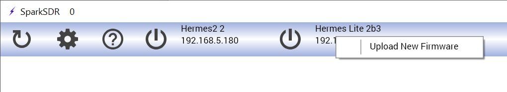
For each link above you need the rbf file, use SparkSDR to load gateware. In SparkSDR right-click on the Hermes-Lite 2 entry, if you have other Hermes / Hermes variants on the network then you see an entry for each radio, so be careful and select the correct entry!
- Close SDR Console.
- Start SparkSDR.
- Right-click on the entry for the Hermes-Lite2 (below).
- Select the new RBF file to be loaded.
- Click Program ., loading new gateware only takes about five seconds.
- Close SparkSDR,
- Start SDR Console.
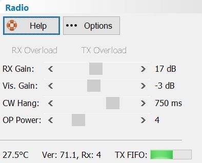
- When you start the HL2 the new gateware will be loaded and ready for use. The gateware version is shown at the bottom of the Radio panel (below).
Options
- RX Gain - there is only one adjustable gain stage in the HL2, the low noise amplifier.
- CW Hang - increase this value to reduce 'relay chatter' - relays switching between dots and dashes.
- OP Power - the output power from the AD9866 which is the heart of the HL2. There are 16 levels of output. See also the Drive option in the transmit DSP.
- Temperature is important - keep your electronics cool! Cooler is always better.
- The gateware major.minor version is show together with the number of receiver slices supported.
- The TX FIFO shows how status of the internal transmit buffers, ideally this is in the middle of the progress bar.
Transmit
Meters
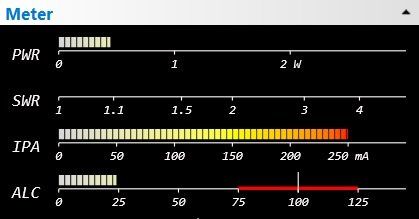
- Power and IPA calibration will be supported in a future release of SDC Console.
- ALC is measured in the modulation components of SDR Console, it is not a traditional hardware-feedback ALC.
Options
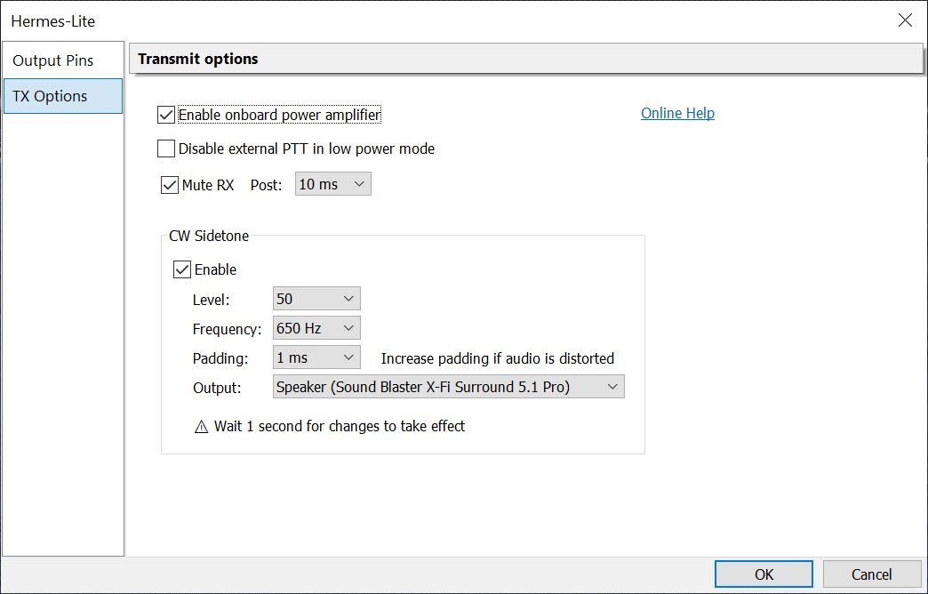
- Enable onboard power amplifier - much be selected if the 5 watt PA is to be used.
- Disable external PTT in low power mode - this is the Q5 switch control - see schematic.
- Mute RX - in transmit you do not want to receive the same data, so the IQ (data) samples are muted while in transmit and for a few milliseconds after transmit ends (Post).
- Filter board - select the filter option.
Output Pins
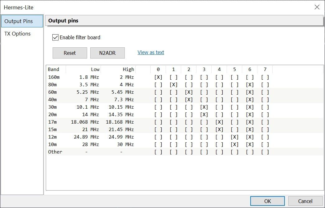
N2ADR Filter Board
| Filter | OC Mask | Frequency |
|---|---|---|
| LPF | x01 | <= 2 MHz |
| x02 | <= 4 MHz | |
| x04 | <= 7.3 MHz | |
| x08 | <= 14.35 MHz | |
| x10 | <= 21.45 MHz | |
| x20 | <= 30 MHz | |
| HPF | x40 | >= 3 MHz |
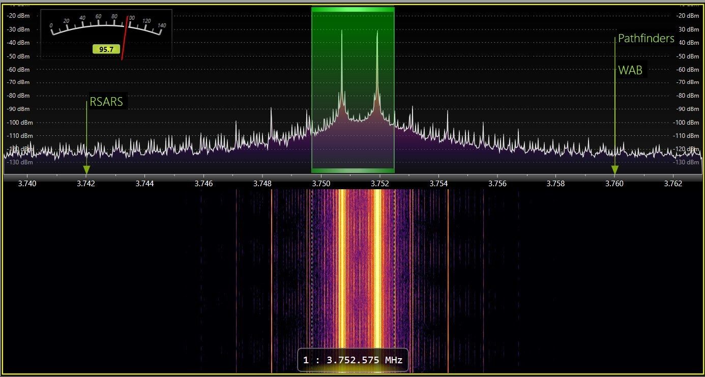
Two-Tone test
Optional RX Input
Note from Steve, November 4th 2019: There is no switching or software control of the optional RX input. If you look at the HL2 schematic on the "RF Frontend" page, you can see that it is just a parallel input from the TR switch.
The main purpose is for more controlled feedback of TX signal to the RX during TX for Pure Signal. You could also use it as an always connected RX input to a different antenna. You can solder coax directly to RF3 on the HL2 and then run the connector to the back panel. There are also a uFL footprint RF4 and RF5 for a removable connection. See
https://www.adafruit.com/product/1661. These provides direct connection to the ADC pre and post LPF. You can run a cable to one of these and remove B81 to disconnect the RX from the TR switch. You either have to disconnect the RX from the TR switch, keep the TR switch always in TX, or remove the TR switch if you want full duplex with the optional RX inputs.